 Trending

Hydraulic Horsepower and Pressure Requirements for Skid Steer Attachments
Skid steers earn their place on construction sites, farms, landscaping projects, and property maintenance jobs because of what they can power. With the right hydraulic attachment, one loader can drill footings, cut trenches, mulch brush, grind stumps, break concrete, sweep pavement, and handle material. Every one of these tasks depends on the loader’s auxiliary hydraulic system to deliver the power the attachment needs.
That power is usually described with three numbers: flow, pressure, and hydraulic horsepower. Flow is measured in gallons per minute (GPM), pressure in pounds per square inch (PSI), and hydraulic horsepower is calculated from both. Specification sheets for loaders and attachments list these figures, and they help buyers, equipment managers, and operators judge whether a machine can run a given tool.
These figures need careful reading. A loader with high pressure may still lack the flow an attachment needs to run at proper speed. A loader with high flow may push more fluid than an attachment can safely accept. A strong horsepower figure looks impressive on paper, but it does not confirm that couplers match, that the return path is suitable, or that a required case-drain line is available. Compatibility depends on the full set of requirements, not on any single number.
Understanding Hydraulic Horsepower
Hydraulic horsepower describes the power available through a hydraulic system. It shows how much work the auxiliary circuit can deliver to an attachment’s motor or cylinders over time. Many demanding attachments, such as mulchers, cold planers, and large trenchers, list a horsepower range or minimum alongside their flow and pressure requirements.
Because horsepower depends on both factors, neither measurement should be considered alone. Two loaders can produce similar horsepower figures in very different ways. One may deliver moderate flow at high pressure, while another delivers high flow at moderate pressure. An attachment designed for one combination may perform poorly on the other.
A system may have high pressure but insufficient flow for an attachment that requires a particular operating speed. Rotating tools such as mulchers and stump grinders, for example, depend on reaching a specific rotor or cutter speed to cut effectively. Without enough flow, they cannot reach that speed regardless of the pressure available.
It also helps to separate engine horsepower from hydraulic horsepower. A loader’s engine rating describes the total power the engine produces. Only part of that power reaches the auxiliary circuit, since the engine also drives the travel system, lift and tilt functions, cooling fans, and other components. Attachment compatibility depends on the auxiliary circuit’s hydraulic output, not the engine rating.
Key takeaway: Hydraulic horsepower reflects flow and pressure working together, so never judge attachment compatibility by horsepower, flow, or pressure alone, and base decisions on the auxiliary circuit’s output rather than the engine rating.
Matching Attachment Requirements
Horsepower, flow, and pressure provide a starting point, but true compatibility depends on the attachment’s full set of requirements. Compatibility should be confirmed before connecting or operating the attachment.
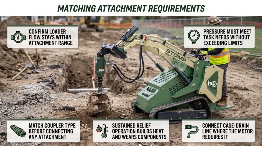
Compare the attachment’s specifications with the loader’s auxiliary system in each of these areas:
- Flow range: Confirm the loader’s auxiliary flow falls between the attachment’s specified minimum and maximum.
- Pressure limits: Confirm the loader’s relief pressure meets the attachment’s operating needs without exceeding its maximum rated pressure.
- Horsepower requirements: Where the attachment lists a hydraulic horsepower range, confirm the loader’s circuit falls within it using the manufacturer’s published figures.
- Hydraulic connection type: Confirm the couplers match in style and size. Many skid steers use flat-face quick couplers, but configurations vary. Never force mismatched couplers together or improvise adapters that are not approved.
- Return requirements: Some attachments need a free-flowing return path to the reservoir. A restricted return can create back pressure that damages motor seals.
- Case-drain needs: Many hydraulic motors require a separate case-drain line that carries internal leakage back to the reservoir at low pressure. Running such a motor without its case drain connected can build pressure inside the motor housing and damage seals or the motor itself.
- Electrical connections: Some attachments use electrical controls for functions such as angling or rotation. Confirm the connector and control system are compatible.
- Capacity and mounting: Confirm the attachment fits the loader’s quick-attach plate, locks fully, and keeps the combined weight of attachment and load within the loader’s rated operating capacity.
Check both the standard and high-flow circuit specifications where applicable. Many loaders equipped with high flow can also operate in standard-flow mode. Confirm which circuit the attachment requires, how to select it, and whether the attachment is permitted on the other circuit. Connecting a standard-flow attachment to an active high-flow circuit can exceed its limits unless the manufacturer specifically approves that configuration. A high-flow attachment on a standard-flow circuit usually runs slowly and may stall under load.
Use the documentation from both manufacturers. Review the attachment manual and the loader’s operator’s manual side by side, and contact the dealer or manufacturer when figures are unclear or missing. A few minutes of confirmation prevents damaged motors, blown seals, overheated systems, and unsafe operating conditions.
Key takeaway: Compare flow range, pressure limits, horsepower requirements, coupler type, return requirements, case-drain needs, and capacity before connecting, and confirm whether the attachment requires the standard or high-flow circuit.
Flow and Attachment Speed
Flow, measured in GPM, affects the speed of hydraulic motors and cylinders. The more fluid that reaches a motor, the faster it turns. The more fluid that reaches a cylinder, the faster it extends or retracts.
Too little flow can reduce performance. Motors turn slowly, cycle times stretch, and cutting tools may fail to reach the speed they need. Operators may then compensate by pushing the loader harder, traveling faster, or forcing the attachment into the work, which increases wear and risk.
Too much flow can exceed attachment limits. Excess fluid can drive a motor faster than its design allows, make cylinder movements abrupt and difficult to control, and force fluid across relief valves. That bypassed fluid turns into heat, which breaks down hydraulic oil, hardens seals, and shortens component life in both the attachment and the loader. In some cases, over-speeding a rotating tool can damage bearings, teeth, or drive components.
Key takeaway: Flow controls the speed of attachment motors and cylinders, so confirm the loader’s actual GPM and keep it within the attachment’s specified range, avoiding both the poor performance of too little flow and the heat and damage caused by too much.
Pressure and Working Force
Pressure, measured in PSI, contributes to the force generated by hydraulic components. When a motor meets resistance, such as an auger bit entering hard clay, pressure rises to push through it. When a cylinder closes grapple jaws around a heavy log, pressure rises to apply clamping force. Higher available pressure allows a motor to produce more torque and a cylinder to apply more force.
Pressure in a hydraulic system builds in response to load. With little resistance, pressure stays relatively low. As resistance increases, pressure climbs until the work moves or the system reaches its relief setting. The loader’s relief valve sets the maximum pressure the auxiliary circuit can reach. Once that limit is reached, the relief valve opens to protect the system, and the attachment slows or stops.
Every component in the circuit, including hoses, couplers, and fittings, must also be rated for the pressure it will carry.
Pressure carries serious safety implications. Fluid escaping from a pinhole leak or damaged hose under pressure can penetrate the skin, even when the leak is too small to see. A fluid injection injury may look minor at first but requires immediate medical attention. Never use your hand to search for a leak.
Key takeaway: Pressure provides the force behind every hydraulic attachment, so confirm the loader supplies enough pressure for the task without exceeding the attachment’s maximum rating, and treat every pressurized component with caution.
Operating and Maintaining the System
Matching an attachment correctly is the first step. Operating it within its limits and maintaining the hydraulic system keeps that match working reliably over time.
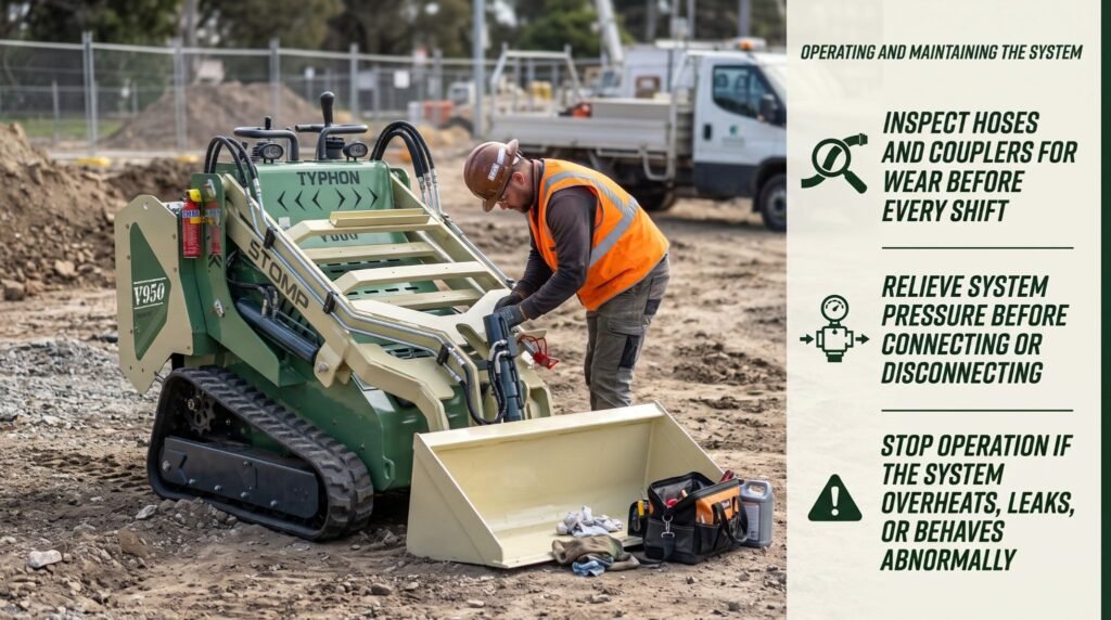
Use the attachment within its recommended flow and pressure range. Avoid running the engine at speeds or settings that push flow beyond the attachment’s limits, and avoid forcing the attachment into work that keeps the system at relief pressure for long periods. Sustained relief operation generates heat quickly and wears components early. Let the tool work at its designed speed, and adjust travel speed or feed rate so it can keep up.
Follow the manufacturer’s procedures for connection and pressure relief. In most cases, this means lowering the attachment to the ground, shutting off the engine, and relieving pressure in the auxiliary circuit using the loader’s approved method before connecting or disconnecting couplers. Trapped pressure can make couplers difficult to engage, damage seals, and release fluid unexpectedly.
Test the attachment in a clear area before starting work. Confirm no workers, vehicles, or obstacles are within reach, run the attachment at low engine speed first, and verify that every function moves in the correct direction and responds smoothly.
Shut down, lower the attachment, relieve pressure, and inspect before continuing. Report any defect that affects safe operation, and keep the loader or attachment out of service until it has been corrected by qualified personnel using approved parts.
Key takeaway: Operate attachments within their recommended flow and pressure range, inspect hoses, couplers, and fluid regularly, relieve pressure before connecting or disconnecting, and stop immediately if the system overheats, leaks, or behaves abnormally.
Conclusion
Hydraulic horsepower, flow, and pressure provide useful information about skid steer attachment performance, but they must be matched to the attachment’s full requirements. Hydraulic horsepower reflects flow and pressure working together, which is why neither number tells the whole story on its own. Flow sets the speed of motors and cylinders, and it must stay within the attachment’s specified range to avoid sluggish performance or excess heat. Pressure provides the working force, and it must meet the attachment’s needs without exceeding its maximum rating. The formula Hydraulic HP = (PSI × GPM) ÷ 1714 offers a practical way to estimate circuit power, provided you treat the result as a theoretical upper limit reduced by real-world losses.
True compatibility goes further than these figures. Coupler type, return requirements, case-drain connections, circuit selection, and rated capacity all need to match before an attachment runs. Once connected, careful operation within recommended limits, regular inspection, and correct pressure relief procedures keep the system dependable. When you confirm compatibility before every connection and maintain the hydraulic system with discipline, your skid steer and its attachments deliver safe, productive, and reliable performance on every job.
FAQs
Does higher hydraulic horsepower mean every attachment will work?
No. Flow, pressure, connection type, and attachment-specific requirements must all match. A loader with strong hydraulic horsepower may still deliver flow outside an attachment’s range, generate pressure above its maximum rating, or lack a required case-drain line or compatible coupler. Compare the attachment manual with the loader specifications in every area before connecting.
Can an attachment use high-flow hydraulics if it requires standard flow?
Only if the attachment and loader instructions permit that configuration. Do not exceed attachment limits. Sending high-flow output to a standard-flow attachment can over-speed motors, make movements difficult to control, and generate excess heat that damages seals and components. Many high-flow loaders can be switched to standard-flow mode, so confirm the correct circuit is selected before operating.
Why is hydraulic horsepower only an estimate?
The calculation does not account for all system losses or the efficiency of the attachment. Pump and motor efficiency, resistance in hoses and couplers, fluid temperature, and mechanical losses in gearboxes and bearings all reduce the power that reaches the tool. In addition, maximum flow and maximum pressure rarely occur at the same time, so the calculated figure represents an upper limit rather than continuous output.
What should be checked before connecting an attachment?
Review flow and pressure requirements, couplers, return and case-drain needs, and the manufacturer’s connection procedure. Confirm which circuit the attachment requires, check horsepower and capacity requirements, and inspect hoses and couplers for damage. Clean both coupler halves, relieve trapped pressure using the approved method, and test the attachment in a clear area before beginning work.